MCP23017-Raspberry
Posted on 10 mai 2016
in Composants
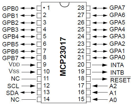
Le MCP23017 utilise 2 broches I2C pins (qui peuvent être partagées avec d’autres périphériques I2C), et en échange, il fournit 16 broches d’utilisation générale en plus qui peuvent être configurées en entrée ou sortie.
Le bus I2C est est pris en charge par les broches.
- SCL : Signal d’horloge. SCL signifie Serial CLock (“horloge série” car ce signal cadence l’échange d’information sur le bus I2C).
Connecté sur Arduino GPIO 2
- SDA : Signal de donnée. SDA signifie Serial DAta (“Donnée série car” car les données sont envoyée en série sur cette ligne).
Connecté sur GPIO 3

La bibliothèque Adafruit permet d’adresser directement les ports de votre composant, utilisable pour Arduino.
Pour raspberry, Adafruit propose aussi une bibliothèque python.
#include <Wire.h>
#include "Adafruit_MCP23017.h"

// Basic pin reading and pullup test for the MCP23017 I/O expander
// public domain!

// Connect pin #12 of the expander to Analog 5 (i2c clock)
// Connect pin #13 of the expander to Analog 4 (i2c data)
// Connect pins #15, 16 and 17 of the expander to ground (address selection)
// Connect pin #9 of the expander to 5V (power)
// Connect pin #10 of the expander to ground (common ground)
// Connect pin #18 through a ~10kohm resistor to 5V (reset pin, active low)

// Output #0 is on pin 21 so connect an LED or whatever from that to ground

Adafruit_MCP23017 mcp;

void setup() {
  mcp.begin();      // use default address 0

  mcp.pinMode(0, OUTPUT);
}


// flip the pin #0 up and down

void loop() {
  delay(100);

  mcp.digitalWrite(0, HIGH);

  delay(100);

  mcp.digitalWrite(0, LOW);
}